 Tricks and Tips : Tricks and Tips :Having Fun with NURBs 101! by Norm Fortier Using NURBs
can be simple and fun! With little
effort, you can create this fun capsule to
launch your characters into space, or any other physical simulation scenario. |
|
|
1 |
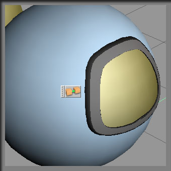
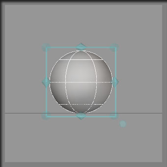
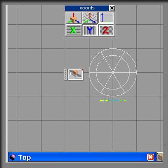
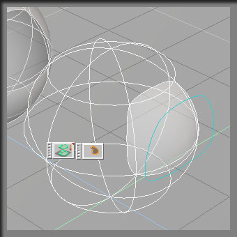
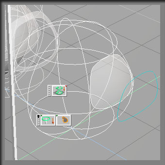
Using default settings for the NURBs sphere Primitive, bring in one sphere and locate this at center of workspace. Location, as defined by the object information panel should read x = 0, y = 0 and z = 1. This will place the sphere as shown in the first image. Placing your object at this location allows us to perform further work on this simple NURBs sphere. As you can see from this initial image, there is already isocurves defining the window we wish to create. Although we can see the shape we want to eventually occupy, we must recreate this using trueSpace NURBs tools. |
|
2 |
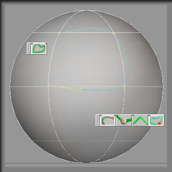
I show the Add Curve tool being used here to draw a crude curve around the perimeter of the window opening we want to use. Although we are using the sphere as a guide, we are creating a flat curve in this process. After we have the curve drawn with three points, we will close the curve in the next phase of the tutorial. |
|
3 |
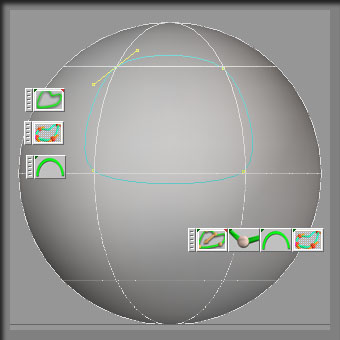
The Close curve tool was used to complete the crude curve. You see to the right, how I have selected the Change Curve Parameters for all points tool and used the Smooth tool to set the attribute on all points. The result is the image showing where our curve is located in relation to the sphere and how defined the curve actually is. You can use the Sharp tool to change the curve attributes into a more square shape if desired. The Smooth works best in this particular scenario. |
|
4 |
From a top view, use the object move tool to locate the curve in front of the sphere. You can see how the x direction/axis has been isolated so we do not move the curve in the x direction/axis. We restrain the movement to y direction/axis. There are times when you will want to zoom in close to position a curve. For purposes of this tutorial, this is not necessary, rather we position this curve once and leave its position static. It is important that you do not reposition the curve during this tutorial because in the end things just will not line up correctly. |
|
5 |
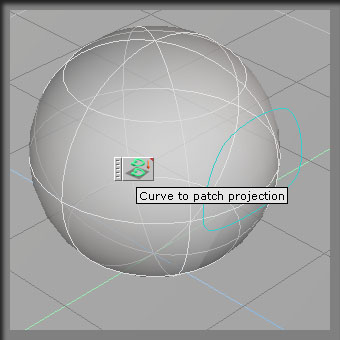
Once located where we want, the curve will be projected onto the surface of the NURBs sphere. Now it is important to mention that I made a copy of the sphere and moved it back out of the way so as not to interfere with the work on this sphere. As the tutorial progresses, you will see copies of objects being used, while the original is always saved/copied for future use if required. The Curve to patch projection tool is displayed in this image. This is the tool used to project curves onto surfaces. |
|
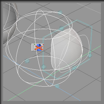
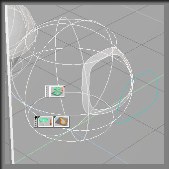
6 |
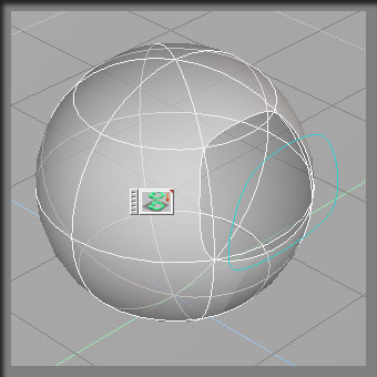
When you use the Curve projection tool on the sphere, we see the hole created in the surface of the sphere. We also see isocurve lines that still exist within the context of the object proper. They have no effect on our work, they just remain visible in all display modes except Solid, which as we see later, will turn all of them invisible. At this point in time we have the basic capsule body shape with the porthole/window carved out of the surface. Now we have to move on to creating some additional peices for the port/window. |
|
7 |
This completes the body of the capsule. Using some of the tools and methods shown above, we will proceed with the additional parts to the object. |
|
8 |
Using another copy of the sphere, position the sphere at location x = 0, y = 0 and z = 1. The curve is still in same position as we left it. We now have a fresh surface (sphere) to project the curve onto again. This time however we have to select the trim outside of patch tool. This in effect gives us the negative image of the body surface. < /SUP > It would be a good idea to make a copy of this object (after converting to no history patch). |
|
9 |
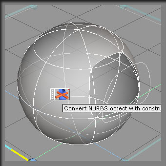
Here again I will stress and show the Convert tool used to remove/destroy the history on the patch. We can not move ahead with further refinement of the patch unless we permanently fix the changes we made thus far. If we did not convert. Simply moving the object will have an effect on the surface. We are or would be still in edit mode and the result would be other than we expect. Once converted, make a copy of the object and move it back out of way behind the object. I always move my copies behind the object I am working on so that when I go into a front view, I can sort of see all the parts and how they are lining up. |
|
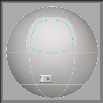
10 |
Here we demonstrate the front view scenario. Notice how things are starting to line up against the sphere in far background. I have selected the curve and scaled it down to a size relative to what you see here. I will now project the curve onto the surface to create an exterior moulding for our port/window. Remember we are using a copy of the surface to work on. This protects us in case of accident or mistake. We can simply delete the bad surface and use another copy of the surface to work on. |
|
11 |
Using the curve projection tool and the Trim Inside of projected curve tool, we project the curve onto the surface and create the interior hole you see. You can adjust the size of the hole if you wanted by selecting the curve and scaling it up or down until you feel comfortable with the size of this end object. Convert the surface to remove the construction history and make a copy of this surface object. Move the copy out of the way to a safe position behind the sphere. |
|
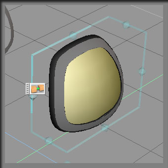
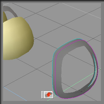
12 |
Using a copy of the surface again, we project the curve onto that surface and this time use the Trim off outside of curve tool to create what I will call the glass portion of the port/window. Again, convert to non history patch and then copy move to a safe location behind the sphere. You can do a quick view in front view to see again how the objects are lining up against the sphere in background. If you see a problem with any of the items, go back and fix now before we move ahead with the next stage of the tutorial. |
|
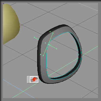
13 |
At this point in time, I went to a solid display mode for the workspace. Notice all those isocurve lines are now invisible. At this stage we really have to be able to see what we are working on and the isocurve lines get in the way. I show the Blend surface tool in the image, as this is the tool we are using. I quickly change my color in material editor to a new color before I begin to blend. This will color our blends with the new color. |
|
14 |
Once the two surfaces are blended, we again wish to do a conversion of the surfaces to remove the history of the patches we blended. Although it will make no difference in this scenario, it is just a good habit/tip to convert your patches. Now we can begin to put the capsule together. |
|
15 |
 Locate the glass portion of the
capsule port/window and locate it to the position you see here. The
molding object is thick enough to afford us the ability to position the
glass so we see a lip of molding infront of and behind the glass
itself. Locate the glass portion of the
capsule port/window and locate it to the position you see here. The
molding object is thick enough to afford us the ability to position the
glass so we see a lip of molding infront of and behind the glass
itself.
Use the Glue as Sibling tool to glue the glass to the molding. |
|
16 |
Make a copy of the sphere/surface that has the port opening cut out of it. Move the copy so it is in a position as demonstrated in this image. Again we can situate the surface closer to the back of the molding. Use your left and top views to ensure you are positioned correctly. We will copy this surface and scale it up ever so slightly. The idea is to have the interior the color you see here, while we will color the exterior (copy) a darker more metalic texture. |
|
17 |
 Here you see the copy, painted
with a darker, metalic shade of the other sphere. We scaled the spher up
ever so slightly to a size that still shows the lip of the molding outside
the exterior part of capsule. Here you see the copy, painted
with a darker, metalic shade of the other sphere. We scaled the spher up
ever so slightly to a size that still shows the lip of the molding outside
the exterior part of capsule.
Use your Glue as Sibling tool to glue the porthole/window to the interior and exterior capsule body parts. We now have a completed capsule. We call this capsule:
trueSpud |
|
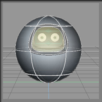
18 |
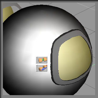
Here I show a different view of the scene. I grabbed a set of eyeball objects from the object library. No face as it sort of looks like in the image, just two eyeballs. I put this object inside the capsule. This angle of shot in solid display mode shows the size of the eyes before we rendered the final image you saw at the very beginning of the tutorial. If you examine the two, you will note that we are seeing a skewed effect between them. This is the accuracy of the render engine at work. I find it most interesting actually. |
|
Summary! |
Hopefully we covered some areas that interest you. This is a most basic example of building objects with nurbs.The curve projection tools make working with NURBs very interesting and enjoyable. With a litle practice, you should be able to work with more complicated objects and ideas. ! |
 Here we show
the final blend to enclose this molding object. If you right click on the
Blend surface tool, you will have the opportunity to set the
tension/smoothness of the blended surface.
Here we show
the final blend to enclose this molding object. If you right click on the
Blend surface tool, you will have the opportunity to set the
tension/smoothness of the blended surface.